1. Hardware
The EPC537N NIM Microcontroller module puts a multiplicity of
universally applicable configuration features at the disposal, which
can be used depending upon requirement totally or partly to the user.
The compilation took place with the target to support both purely
similar and digital applications. The configuration is limited mainly
by the available workstation on the front plate of a
1/12-NIM-Einschubs with the use the common sockets of the series of
NIM CAMAC S00.
1,1 configuration features
An outline of the available " features " of the hardware
gives the following enumerating:
| Port NR. | Function |
|---|---|
| P1 | 8-bit-bi-directional I/O |
| P3 | 4-Bit-Bidirektionale I/O, INTERRUPT |
| P4 | 8-bit-bi-directional I/O |
| P5 | 8-bit-bi-directional I/O |
| P7 | 8-Bit-Inp/ADC |
1,2 plug arrangement and steckerbelegung
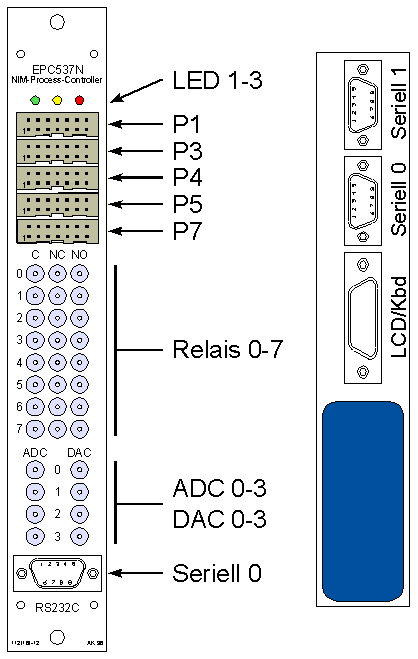
The following figures show the position of the plug
connectors at the front plate and at the rear side of the NIM
CONTROLLER. The defined links are continued to describe in the link.

| Pin | P1 | P3 | P4 | P5 | P7 |
|---|---|---|---|---|---|
| 1 | P1.0 | Vcc(+5V) | P4.0 | P5.0 | P7.0/ADC |
| 2 | Gnd | Gnd | Gnd | Gnd | Gnd |
| 3 | P1.1 | Vcc(+5V) | P4.1 | P5.1 | P7.1/ADC |
| 4 | Gnd | Gnd | Gnd | Gnd | Gnd |
| 5 | P1.2 | P3.2 | P4.2 | P5.2 | P7.2/ADC |
| 6 | Gnd | Gnd | Gnd | Gnd | Gnd |
| 7 | P1.3 | P3.3 | P4.3 | P5.3 | P7.3/ADC |
| 8 | Gnd | Gnd | Gnd | Gnd | Gnd |
| 9 | P1.4 | P3.4 | P4.4 | P5.4 | P7.4/ADC |
| 10 | Gnd | Gnd | Gnd | Gnd | Gnd |
| 11 | P1.5 | P3.5 | P4.5 | P5.5 | P7.5/ADC |
| 12 | Gnd | Gnd | Gnd | Gnd | Gnd |
| 13 | P1.6 | Vcc(+5V) | P4.6 | P5.6 | P7.6/ADC |
| 14 | Gnd | Gnd | Gnd | Gnd | Gnd |
| 15 | P1.7 | Vcc(+5V) | P4.7 | P5.7 | P7.7/ADC |
| 16 | Gnd | Gnd | Gnd | Gnd | Gnd |
Port the P1, P3, P4 and P5
can be used as output input and output for TTL signals. If
an input is to take place of port line, then the output register of
the appropriate port at the bit position of the line must indicate a "
1 ". In this way it is possible to use output input and output on a
port mixed.
Port P7 can be used for TTL signals only as entry
port. Additionally the processor-internal ADC (8+2 bits dissolution)
uses these lines for the measurement of voltages, why the lines of P7
are decoupled by an inserted input operation amplifier also. The
voltage to all port must be situated within the operating voltage area
of the Microcontrollers (Gnd - 5.0V), in order to avoid destruction of
the CONTROLLER.
The wiring of the eight relays , which
indicate a nominal contact rating of 1.0A/30V and a max. permanent
current of 2.0A, can be inferred from the following sketch. It
concerns eight independently adjustable two-way contacts with a
resting (numerical control) and a make contact (NO).

The four 12-Bit of ADC inputs ADC 0-3
indicate an input voltage section of 0.00V - 5.00V and an input
impedance of 1kOhm. They are decoupled and against overvoltage
protected by one operation amplifier each. The signal of all four
channels can be transferred by the use of four separated ADCs parallel
and thus at the same time to those the ADCs upstream T/H levels.
Likewise a voltage range of 0.00V - 5.00V take the four
separated adjustable 12-Bit off of DAC outputs DAC 0-3
. These outputs in a the position are by output buffer
amplifiers to drive 50Ohm-Lasten.
The serial interface 0 , over which the
monitor program of the NIM CONTROLLER is served, is accessible at the
front plate and at the rear side of the module. Only the signals TxD
and RxD are used, the lines DSR and DTR or RTS and CTS are connected
in each case. The 9-polige plug points the generally usual allocation
to (2=RxD, 3=TxD, 5=Gnd).
The serial interface 1 , which is available
only at the rear side of the module, indicates the same pin allocation
as the interface 0. The software does not make use of this interface,
it in the standard version can however by user programs be used.
The link for the LCD/Kbd module is herausge
at the rear side of the module leads and indicates the lines necessary
for the control of an LCD with function keys.
2. Software
The inserted software of the NIM CONTROLLER is inevitably
very generally held, since the CONTROLLER should be universally usable
and the special task from application can be different to application.
The following list of the " software features " gives a short overview of the characteristics of the inserted EPC monitor program, with whose assistance of the NIM CONTROLLER can be served:
The EPC monitor program is served by means of text commands, which are transmitted to the serial interface 0 of the CONTROLLER. The controlling computer needs only a serial interface with the signals TxD, RxD and Gnd. The link effected usually with one sucked. Modem eliminator cable, which exchanges the lines TxD and RxD. For transferring the commands and for the output of the return values of the EPC of monitor almost any terminal program can be used. The interface 0 of the NIM CONTROLLER is initialized with the RESET (= switching on on) by the EPC monitor on the following adjustment:
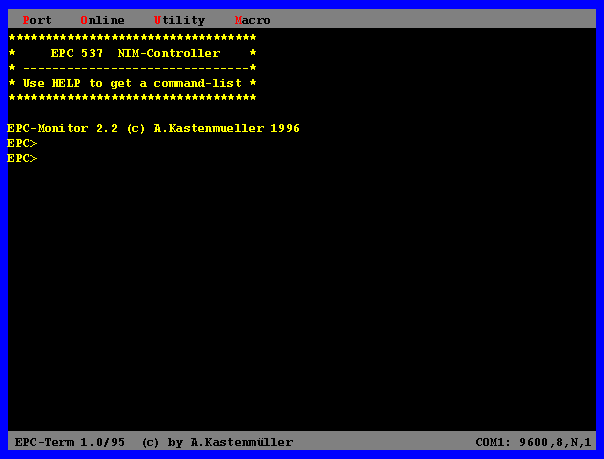
Since the EPC monitor sends the received characters back to the interface, local echo must be stopped in the terminal program to off. When switching on on the monitor program announces itself with the following output, before it transmits and for > instruction inputs waits command-promptly the EPC:
2,3 selection of fundamental commands
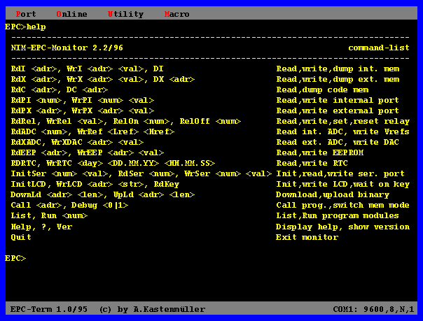
One of the simplest commands without additional parameters is the HELP - command, also by in ? to be abbreviated can. It arranges to output the monitor a short overview of all available commands:
1. General remarks on the EPC monitor
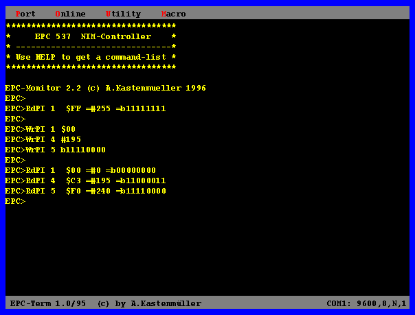
The EPC monitor is served over the serial interface 0 the
SAB80C537-Microcontrollers. For communication with PC or another
controlling computer almost any terminal program can be used, be used
there commands, parameters and outputs of the EPC monitor only ASCII
character.
The interface of the EPC80537 is initialized with the RESET by the EPC
monitor on the following adjustment:
Since the EPC monitor sends the received characters back to the interface, local echo must be stopped in the terminal program to off.
1,1 starting procedure of the EPC monitor
After the initialization the EPC monitor checks whether a
program module is available starting from the address $8000 in the
EPROM and this the status " autostart " has. In the EPROM if no
program module is found, then the EPC monitor in the RAM looks $8000
up starting from address for an autostart module. If an autostart
module was found, after a time delay of approx. 5s, which gives the
possibility to the user to abort by an input over the serial interface
the starting procedure that is started found module. Contained
neither the EPROM nor RAM the valid autostart module, then directly
command-promptly of the EPC monitor appears.
1,2 command line of the EPC monitor
1,3 form of the command parameters
Scope: 0 - F
Scope: 0 - 255 (decimally)
| Format | Example |
|---|---|
| binary | b10100011 |
| decimally | #237 |
| in hexadecimals | $1f |
Scope: 0000 - FFFF (in hexadecimals)
Example: $$F6C9
1,4 return values of the EPC monitor
| RdI | READ from internal RAM |
|---|
| Description: | Reading from data from the internal RAM of the 80C537 |
| Format: | RdI < address > byte Par |
| Parameter: | Address $00-$ff |
| WrI | Write to internal RAM |
|---|
| Description: | Writing of data in internal RAM of the 80C537 |
| Format: | WrI < address > byte Par < value > byte Par |
| Parameter: | Address $00-$ff
Worth $00-$ff |
| DI | Dump internal RAM |
|---|
| Description: | Reading and representing of all contents internal RAM of the 80C537 in hexadecimal and ASCII form |
| Format: | DI |
| RdX | READ from external RAM |
|---|
| Description: | Reading from data from the external RAM of the 80C537 |
| Format: | RdX < address > Word Par |
| Parameter: | Address $0000-$ffff |
| WrX | Write to external RAM |
|---|
| Description: | Writing of data in external RAM of the 80C537 |
| Format: | WrX < address > Word Par < value > byte Par |
| Parameter: | Address $0000-$ffff
Worth $00-$ff |
| DX | Dump external RAM |
|---|
| Description: | Reading and representing from 256 bytes external RAM of the 80C537 in hexadecimal and ASCII form |
| Format: | DX < address > Word Par |
| Parameter: | Address $0000-$ffff |
| RdC | READ from code MEMORY |
|---|
| Description: | Reading from data from the program memory of the 80C537 |
| Format: | RdC < address > Word Par |
| Parameter: | Address $0000-$ffff |
| DC | Dump code MEMORY |
|---|
| Description: | Reading and representing from 256 bytes of the program memory of the 80C537 in hexadecimal and ASCII form |
| Format: | DC < address > Word Par |
| Parameter: | Address $0000-$ffff |
| RdPI | READ from internal port |
|---|
| Description: | Reading from data of an internal processor port of the 80C537 |
| Format: | RdPI < port NR > Num Par |
| Parameter: | Port NR 0-8 |
| WrPI | Write to internal port |
|---|
| Description: | Writing of data into an internal processor port of the 80C537 |
| Format: | WrPI < port NR > byte Par < value > byte Par |
| Parameter: | Port NR 0-6
Worth $00-$ff |
| RdPX | READ from external port |
|---|
| Description: | Reading from data of an external port of the EPC80537 with MEMORY mapped I/O within the range of $$FF00-$FFFF |
| Format: | RdPX < address > byte Par |
| Parameter: | Address $00-$ff (accordingly $$FF00-$FFFF) |
| WrPX | Write to external port |
|---|
| Description: | Writing of data into an external port of the EPC80537 with MEMORY mapped I/O within the range of $$FF00-$FFFF |
| Format: | WrPX < address > byte Par < value > byte Par |
| Parameter: | Address $00-$ff (accordingly $$FF00-$FFFF)
Worth $00-$ff |
| RdEEP | READ from EEPROM |
|---|
| Description: | Reading from data from the EEPROM |
| Format: | RdEEP < address > byte Par |
| Parameter: | Address $00-$ff (dependent on the EEPROM type) |
| WrEEP | Write to EEPROM |
|---|
| Description: | Writing of data into the EEPROM |
| Format: | WrEEP < address > byte Par < value > Word Par |
| Parameter: | Address $00-$ff (dependent on the EEPROM type)
Worth $0000-$ffff |
| RdRTC | READ really time Clock |
|---|
| Description: | Reading from date and time-of-day from the real-time clock |
| Format: | RdRTC |
| WrRTC | Write to really time Clock |
|---|
| Description: | Writing of date and time-of-day into the real-time clock |
| Format: | WrRTC < weekday > Num Par < date > TT.MM.JJ < time-of-day > HH.MM.SS |
| Parameter: | Weekday 0-6 (0=So, 1=Mo... 6=Sa)
Date TT.MM.JJ (firmly given format) Time-of-day HH.MM.SS (firmly given format) |
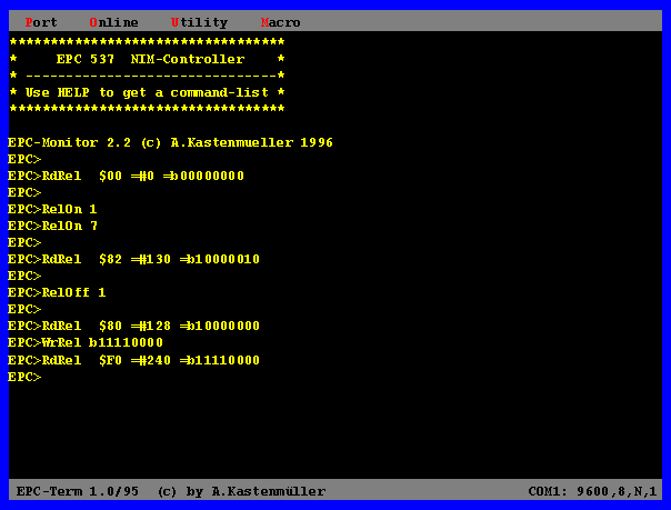
| RdRel | READ Relay status |
|---|
| Description: | Reading of the relay status |
| Format: | RdRel |
| WrRel | Write Relay status |
|---|
| Description: | Writing of the relay status as 8-bit word |
| Format: | WrRel < value > byte Par |
| Parameter: | Worth $00-$ff bit pattern for relay status |
| RelOn | Relay on |
|---|
| Description: | Switch on a relay |
| Format: | RelOn < relay NR > Num Par |
| Parameter: | Relay NR 0-7 |
| RelOff | Relay off |
|---|
| Description: | Switch off a relay |
| Format: | RelOff < relay NR > Num Par |
| Parameter: | Relay NR 0-7 |
| WrRef | Write ADC Reference volume daily |
|---|
| Description: | Adjust that reference reference now genereference now gene of the internal ADC of the EPC80537 |
| Format: | WrRef < VGnd > Num Par < VRef > Num Par |
| Parameter: | VGnd 0-C (according to the following table)
VRef 0,4-F (according to the following table) |
| VGnd/VRefMode | lower reference | upper reference |
|---|---|---|
| 0 | 0.0000 | 5.0000 |
| 1 | 0.3125 | - |
| 2 | 0.6250 | - |
| 3 | 0.9375 | - |
| 4 | 1.2500 | 1.2500 |
| 5 | 1.5625 | 1.5625 |
| 6 | 1.8750 | 1.8750 |
| 7 | 2.1875 | 2.1875 |
| 8 | 2.5000 | 2.5000 |
| 9 | 2.8125 | 2.8125 |
| A | 3.1250 | 3.1250 |
| B | 3.4375 | 3.4375 |
| C | 3.7500 | 3.7500 |
| D | - | 4.0625 |
| E | - | 4.3750 |
| F | - | 4.6875 |
| RdADC | READ ADC Channel |
|---|
| Description: | Execute a AD transformation at a ADC channel of the 80C537 |
| Format: | RdADC < channel > Num Par |
| Parameter: | Channel 0-B (according to P7.0 - P7.7, P8.0 - P8.3) |
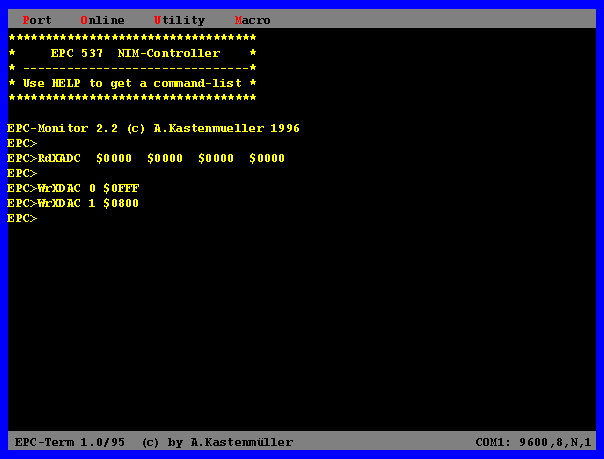
| RdXADC | READ external ADC |
|---|
| Description: | Execute a simultaneous AD transformation at the 4 external 12-Bit ADCs |
| Format: | RdXADC |
| WrXDAC | Write to external DAC |
|---|
| Description: | Output of an analog value on one of the 4 external 12-Bit SINCE transducer |
| Format: | WrXDAC < DAC NR > Num Par < value > Word Par |
| Parameter: | DAC NR 0-3
Worth $0000-$0fff (12-bit value) |
| Init LCD | Initialize LCD |
|---|
| Description: | Initializing and deletion LCD |
| Format: | Init LCD |
| WrLCD | Write to LCD |
|---|
| Description: | Output from text on the LCD |
| Format: | WrLCD < address > byte Par < text > stringer |
| Parameter: | Address: $00-$ff (address in the memory LCD)
Text: ASCII character (output only in uppercase letters) |
| RdKey | READ key board |
|---|
| Description: | Control rooms on a depressing the key at the LCD/KEY board or a character at Ser0 |
| Format: | RdKey |
| Output: | Bit pattern of the pressed keys (bit 0-4) |
| InitSer | Init Serial port |
|---|
| Description: | Adjust the transfer parameter of the serial interfaces of the EPC80537 |
| Format: | InitSer < port NR > Num Par < mode > Num Par |
| Parameter: | Port NR 0-1
Mode 0-9 (according to the following table) |
| Mode | Baud rate serial 0 | Baud rate serial 1 |
|---|---|---|
| 0 | 150 | - |
| 1 | 300 | - |
| 2 | 600 | - |
| 3 | 1200 | - |
| 4 | 2400 | - |
| 5 | 4800 | 4800 |
| 6 | 9600 | 9600 |
| 7 | 19200 | 19200 |
| 8 | - | 38400 |
| 9 | - | 57600 |
| WrSer | Write to of Serial port |
|---|
| Description: | Transmit a byte at a serial interface of the 80C537 |
| Format: | WrSer < port NR > Num Par < value > byte Par |
| Parameter: | Port NR 0-1
Worth $00-$ff |
| RdSer | READ from Serial port |
|---|
| Description: | Read a byte of serial Schnittstelledes a 80C537 |
| Format: | RdSer < port NR > Num Par |
| Parameter: | Port NR 0-1 |
| Downld | Download to external RAM |
|---|
| Description: | Load a number of bytes in the binary format to an address in the external RAM of the EPC80537 |
| Format: | Downld < address > Word Par < length > Word Par |
| Parameter: | Address $0000-$ffff
$0000-$ffff (number of the bytes) lengthens |
| Flow: | Start of the Downloads after the message " Download
active.... "
End after the message " finished Checksum $$xx " The check total is calculated as total of all received bytes without Carry and in hexadecimals output. |
| Upld | Upload from external RAM |
|---|
| Description: | Read a number of bytes in the binary format of an address in the external RAM of the EPC80537 |
| Format: | Upld < address > Word Par < length > Word Par |
| Parameter: | Address $0000-$ffff
$0000-$ffff (number of the bytes) lengthens |
| Flow: | Start of the Uploads after the message "< CR >
for start...
" and transmitting a character without echo. End after the message " finished Checksum $$xx " The check total is calculated as total of all transmitted bytes without Carry and in hexadecimals output. |
| Call | Call to of Program |
|---|
| Description: | Call of a program in the code MEMORY |
| Format: | Call < address > Word Par |
| Parameter: | Address $0000-$ffff (branch address) |
| Debug | SWITCH MEMORY configuration |
|---|
| Description: | Switch the memory configuration between Debug mode (program partly in the RAM) and normal mode (program completely in the ROM/CEprom) |
| Format: | Debug < mode > Num Par |
| Parameter: | Mode 0 = normal mode (ROM)
Mode 1 = Debug mode (RAM) |
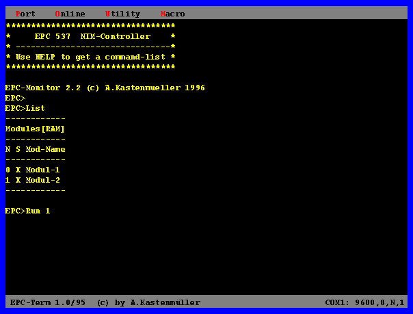
| Cunning | Cunning Modules |
|---|
| Description: | Display the available program modules in the ROM or RAM with number, status and name |
| Format: | Cunning |
| Run | Run Program of modules |
|---|
| Description: | Start a program Modules in the ROM or RAM |
| Format: | Run < module NR > Num Par |
| Parameter: | Module NR 0-F |
| Version |
|---|
| Description: | Output of the program version number of the EPC monitor over the serial interface |
| Format: |
| Help | Help |
|---|
| Description: | Output of a command outline of all available commands of the EPC monitor |
| Format: | Help or? |
| Quit | Quit EPC monitor |
|---|
| Description: | Terminate the EPC monitor |
| Format: | Quit |
3. Creation of completing program modules
3,1 bases
The EPC monitor supports the supplement of the
function range with
the commands CUNNING
and RUN by user specific modules, which can be produced with different
development tools. It must be available only the possibility, when
result to assemble or compile a file with object code for a certain
address. These max. 16 program modules, which itself in the EPROM
(Debug 0) or in (Nonvolatile)RAM (Debug 1) to rule can, begin in each
case with a header, which contains information apart from the name and
the status of the module also for the concatenation of the modules.
The header of the first program module always is at the address $8000
in the EPROM or RAM. The addresses of the following modules result
then in each case from the length of the preceding modules.
In this description with the programming of Microcontrollern
one does not deal, which is represented in detail in various drawer
books. In particular the CONTROLLERS of the so-called 8051-Serie and
their Siemens derivatives (e.g. the used SAB80C537) are topic of a
multiplicity of publications.
Only the necessary information is given here, in order to
develop successfully with appropriate development tools modules, which
can be inserted into the concept of the EPC monitor.
3,2 paging
The memory of the 80C537-Controllers covers 64kByte for
program code and 64kByte for data. The address decoding of the
CONTROLLER hardware permits a partial over-dazzles these areas, in
order to be able to execute programs, which were loaded first in the
data area, afterwards. The program memory range from $0000-$7fff is
not to the user at the disposal, since this is reserved for the BIOS
and the EPC monitor. Within the range of $8000-$ff00 both the program
memory knows (EPROM) and the memory (RAM) for program modules to be
used. Switching between both areas concerning the position of the
program code takes place with the Debug instruction of the monitor.
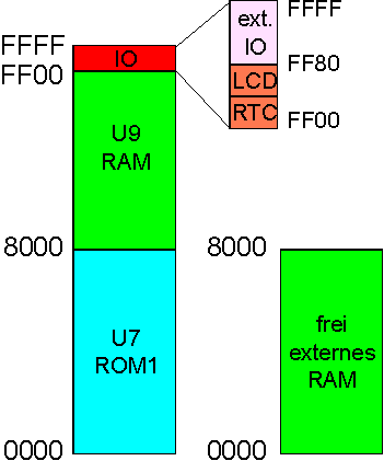
The range from $$FF00-$FFFF the memory is used as port area for the control of hardware components and can be read nor described neither, since any accesses in addresses within this area to I/O accesses are rerouted.
The allocation of the storage areas is shown in the following diagrams:
Image mode (Debug 0): Separate program and memory too for each 64KByte
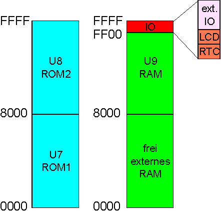
Debug mode (Debug 1): Insertion RAM ($8000-$ff00) into the program memory
3,3 structure of modules
The program modules are stored as chained list starting from
the address $8000 in the memory of the CONTROLLER. Each module
receives a special header, which contains a pointer apart from
additional information about the module also on the beginning of the
following module.
The header of a module is 16 byte long and has the following
determined structure:
| Address | Use | Assertion |
|---|---|---|
| 00h-01h | Identifier | ' AK ' |
| 02h | Status | ' A ' = autostart
' X ' = Executable |
| 03h | Check total | Check total over the program code, which follows after the header and is calculated up to the value of the pointer after the next module as simple byte total without transfer. |
| 04-05h | Pointer | Pointer on the beginning of the next module header or behind the end of the present module (format: LSB:MSB) |
| 06h | unused | - |
| 07h-0Eh | Text | Text, which is displayed of CUNNING as module name. |
| 0Fh | End label | 00h |
If the first module (at address $8000) has the status A
(autostart), then it is started by the EPC monitor directly after
switching on of the NIM CONTROLLER on, if within 5s a character at the
serial interface will not receive. This offers the possibility of
using the NIM CONTROLLER with a fixed program without a controlling
terminal for determined functions.
The program code must begin directly after the module header,
since the call takes place via an LCALL instruction to the offset
address $0010 from the beginning of the module header. A return to
command-promptly the EPC monitor is possible by an RET instruction in
the program code, whereby it must be guaranteed that the stack of the
system is again in the initial state. Since the program code is
branched to directly, it must be for the respective address assembled
or reloziert (e.g. the code for module 0 begins with $8010). This is
to be considered in particular with successive modules, whereby for
each module also the necessary header must be considered. The
simplest possibility of ensuring this is the linkage of all headers
and Object files to a file, which afterwards to the address $8000 into
RAM of the EPC is loaded or into a 32k-EPROM burned.
An example of a simple module is the following assembler program:
;******************************************************************************
Demo program for a program module, which can be assembled with
TASM;******************************************************************************
last modification:  08.04.1996;    Function:  The middle light
emitting diode is to flash 10x;    # INCLUDE " SFR80537.DEF ";
Mnemonics for SFRs

# INCLUDE " NIMCTRL.EQU ";  Label definitions for BIOS routines

ModStart equ $8000;  Start address of the first module HeaderLen equ
$0010;  Length of the module header

org ModStart + HeaderLen

-------------------------- start module code
-------------------------------  Code start push ACC;  Registers on
stack protect push lcall LEDòff to B;  LED2 switch mov B off, #10;
Mov A, #250 set counter initial value on 10;  Delay 250ms loop lcall
LEDòn;  LED2 switch lcall Delms on;  Delay lcall LEDòff;  LED2
switch lcall Delms off;  Delay djnz B, loop;  Pop B pass through loop;
Registers of the stack get pop ACC ret;  --------------------------
end module code -------------------------------- end
The composition of modules to a file and the automatic production of the necessary headers are possible with the program COMPMOD. As input serves a simple text file, which contains the necessary information for the concatenation of the individual Object files:
;    Name[max.8], Status[1], Adresse[hex], file name;
Modul-1, X, 8000, OCMcPcMcOcD1.cOcBcJ Modul-2, X, 8100,
OCMcPcMcOcD2.cOcBcJ
COMPMOD.EXE the name of this file transferred as command line parameters (e.g. COMPMOD.MDL) and the specified Object files to be situated in the same directory. After the execution of COMPMOD there is a new file with the Extension MOD (e.g. COMPMOD.MOD), which can be loaded directly to the address $8000 and all modules contains. Loading of the file takes place with the help of the instruction Downld of the EPC monitor and a terminal program. Particularly comfortably this is possible with the program EPCTERM, since this takes over also the examination of the check total. After switching into the Debug mode it can be checked with CUNNING whether the modules are as desired available.
3,4 use of BIOS routines
The control of the hardware of the NIM CONTROLLER requires
usually special knowledge of the circuit and the internal mode of
operation of the assigned components. In order to simplify
programming, there are already BIOS routines, which are contained in
the EPROM for all important functions. These can be used, as the list
of the re-entry point addresses is merged NIMCTRL.EQU into the source
text of the module and the respective routine with a simple LCALL is
branched to. Almost all parameters of the following routines are
transferred as register contents.
;****************************************************************************** * General routines of the EPC BIOS *;****************************************************************************** ----------------------------------------------------------------------------; Delms; Produces a time delay around n ms (n in A); ----------------------------------------------------------------------------; ********************* external port area FF00-FFFF ************************; ----------------------------------------------------------------------------; RdExtPort; External port (addr in B 00-FF) read; Worth in A; ----------------------------------------------------------------------------; WrExtPort; External port (addr in B 00-FF) write; Worth in A; ----------------------------------------------------------------------------; ************************* serial interface 0 **************************; ----------------------------------------------------------------------------; InitSer0; Initialization Ser0 (A=xxxxx000 < 150Baud to A=xxxxx111 > 19200 Baud); ----------------------------------------------------------------------------; WaitTI0; Control rooms, to interface 0 transmit ready; ----------------------------------------------------------------------------; SendStr0; Transmit a stringer from the code at Ser0 (addr in DPTR, end of the Strings=00h); ----------------------------------------------------------------------------; ************************* serial interface 1 **************************; ----------------------------------------------------------------------------; InitSer1; Initialization Ser1 (A=xxxx0100 < 2400 Baud to A=xxxx1001 > 57600 Baud); ----------------------------------------------------------------------------; WaitTI1; Control rooms, to interface 1 transmit ready; ----------------------------------------------------------------------------; S endStr1 ; Senden eines Strings aus dem Code an Ser1 (Adr in DPTR, Ende des Strings=00h) ; ----------------------------------------------------------------------------- ; ****************************** EEPROM NS93C46 ******************************* ; ----------------------------------------------------------------------------- ; WrEEPW ; Schreiben eines Words (R1,R0) an die Adr. A in das EEPROM ; ----------------------------------------------------------------------------- ; RdEEPW ; Lesen eines Words (R1,R0) an die Adr. A aus dem EEPROM ; ----------------------------------------------------------------------------- ; **************************** Echtzeituhr 72421 ****************************** ; ----------------------------------------------------------------------------- ; InitRTC ; Rü cksetzen der RTC: So 01.01.95 00:00:00, keine Interrupts ; ----------------------------------------------------------------------------- ; GetDate ; Lesen des Datums (BCD): R2=Tag,R3=Monat,R4=Jahr,R5=Wochentag (So=0) ; ----------------------------------------------------------------------------- ; SetDate ; Schreiben des Datums (BCD): R2=Tag,R3=Monat,R4=Jahr,R5=Wochentag (So=0) ; ----------------------------------------------------------------------------- ; GetTime ; Lesen der Uhrzeit (BCD): R2=Sek,R3=Min.,R4=Std ; ----------------------------------------------------------------------------- ; SetTime ; Schreiben der Uhrzeit (BCD): R2=Sek,R3=Min.,R4=Std ; ----------------------------------------------------------------------------- ; ************************* LCD-Anzeige mit HD44780 *************************** ; ----------------------------------------------------------------------------- ; InitLCD ; Initialisieren der LCD (8-Bit Interface, Cursor Off, Clear Display) ; ----------------------------------------------------------------------------- ; WrLCDz1 ; WrLCDz2 ; Ausgabe eines Textes (Code-Adr. in DPTR) in Zeile 1 oder 2 (Txt-Ende = 00h) ; ----------------------------------------------------------------------------- ; GetKey ; Einlesen der LCD-Keys (Bit-Muster in A, LSB=Taste1) ; ----------------------------------------------------------------------------- ; ***************************************************************************** ; * Routinen zur Ansteuerung der zus ä tzlichen Hardware des NIM-Controllers * ; ***************************************************************************** ;******************************* LED - Routinen ******************************* ; ----------------------------------------------------------------------------- ; LED1On ; LED2On ; LED3On ; LEDxOn schaltet eine Leuchtdiode (x=1-3) ein ; ----------------------------------------------------------------------------- ; LED1Off ; LED2Off ; LED3Off ; LEDxOff schaltet eine Leuchtdiode (x=1-3) aus ; ----------------------------------------------------------------------------- ;*************************** Relais - Routinen ******************************** ; ----------------------------------------------------------------------------- ; ReadRel ; ReadRel liest den Zustand der Relais ein (Wert in A) ; ----------------------------------------------------------------------------- ; WriteRel ; WriteRel schreibt einen Zustand in die Relais (Wert in A) ; ----------------------------------------------------------------------------- ; SetRel ; SetRel schaltet ein Relais ein (Nummmer 0-7 in A) ; ----------------------------------------------------------------------------- ; ResetRel ; ResetRel schaltet ein Relais aus (Nummmer 0-7 in A) ; ----------------------------------------------------------------------------- ;************************* externe DAC-Routinen ******************************* ; ----------------------------------------------------------------------------- ; ShiftDAC ; ShiftDAC gibt ein 12-Bit-Wort (R1,R0) an die DACs aus (ohne LOAD-Impuls) ; ----------------------------------------------------------------------------- ; LoadAllDAC ; LoadAllDAC gibt einen LOAD-Impuls an alle DACS parallel ; ----------------------------------------------------------------------------- ; LoadDAC ; LoadDAC gibt einen LOAD-Impuls an einen DAC (Nr. 0-3 in A) ; ----------------------------------------------------------------------------- ;************************* externe ADC-Routinen ******************************* ; ----------------------------------------------------------------------------- ; ReadExtADC ; Gleichzeitiges Einlesen der Werte der externen 12-Bit ADCs (0-3); ; Ergebnisse in (R1:R0, R3:R2, R5:R4, R7:R6) ; ----------------------------------------------------------------------------- ; ***************************************************************************** ; * Routinen des EPC-Monitors f ü r Schnittstelle seriell 0 * ; ***************************************************************************** ; ----------------------------------------------------------------------------- ; GetNumPar ; Wertet Ziffern-Param. (0-F) im Kommandopuffer aus (Wert- >A; C=1:Fehler) ; ----------------------------------------------------------------------------- ; GetBytePar ; Wertet Byte-Param.(bin,dez,hex) im Kommandopuffer aus (Wert->A; C=1:Fehler) ; ----------------------------------------------------------------------------- ; GetWordPar ; Wertet Word-Param. (hex) im Kommandopuffer aus (Wert- >DPTR; C=1:Fehler) ; ----------------------------------------------------------------------------- ; SendZi ; Senden einer ASCII-Ziffer (bin ä rer Wert in A) ; ----------------------------------------------------------------------------- ; SBinByte ; Senden des Akkus in bin ä rer Form ; ----------------------------------------------------------------------------- ; SDezByte ; Senden des Akkus in dezimaler Form ; ----------------------------------------------------------------------------- ; SHexByte ; Senden des Akkus in hexadezimaler Form ; ----------------------------------------------------------------------------- ; SendPortByte ; Sendet ein Byte (Akku) in Hexadezimaler,dezimaler und bin ä rer Form ; -----------------------------------------------------------------------------
3.5 Verwendung von Interrupts
Das Interrupt-Konzept des SAB80C537-Controllers kann den bereits erw
ä
hnten Fachb
ü
chern oder den
Datenbl
ä
ttern zum SAB80C537 entnommen werden. Um den Benutzer in die Lage zu versetzen, auf Interrupts
zu reagieren, werden alle Interrupts auf Adressen im Bereich $FEC0-$FF00 umgeleitet, wobei f
ü
r jeden Interrupt
ein Bereich von 4 Bytes reserviert ist. Dies reicht aus, um durch einen erneuten JMP-Befehl die gew
ü
nschte
Interrupt-Service-Routine anzuspringen.
Die Zuordnung der Adressen zu den Interrupt-Quellen ist wie folgt:
| Einsprungadresse | Interrupt-Quelle |
|---|---|
| FEC0h | IE0 |
| FEC4h | TF0 |
| FEC8h | IE1 |
| FECCh | TF1 |
| FED0h | RI0 & TI0 |
| FED4h | TF2 & EXF2 |
| FED8h | IADC |
| FEDCh | IEX2 |
| FEE0h | EX3 |
| FEE4h | IEX4 |
| FEE8h | IEX5 |
| FEECh | IEX6 |
| FEF0h | RI1 & TI1 |
| FEF4h | CTF |