Now, we can study PA-PB-NC counters for charged particles. For gain tune and TOF origin determination, we need a detailed Monte-Carlo simulation, and such a simulation is performed by Fukuda by GEANT 3.21. To caluculate 1/beta, PA-PB or PA-NC TOF is simulated and divided by the distance between detection points on PA and PB or NC, hence this table is directly applicable to the data.
First, we confirm the PA performance with the correlation between pulse height up/down ratio (horizontal) and down-up time difference (nsec unit, vertical). We should see a positive correlation for each counter, by which proper channel assignment is confirmed, and attenuation length is known. PA attenuation length is deduced to be about 2*L/ln(2.0/0.5) ~ 50 cm.
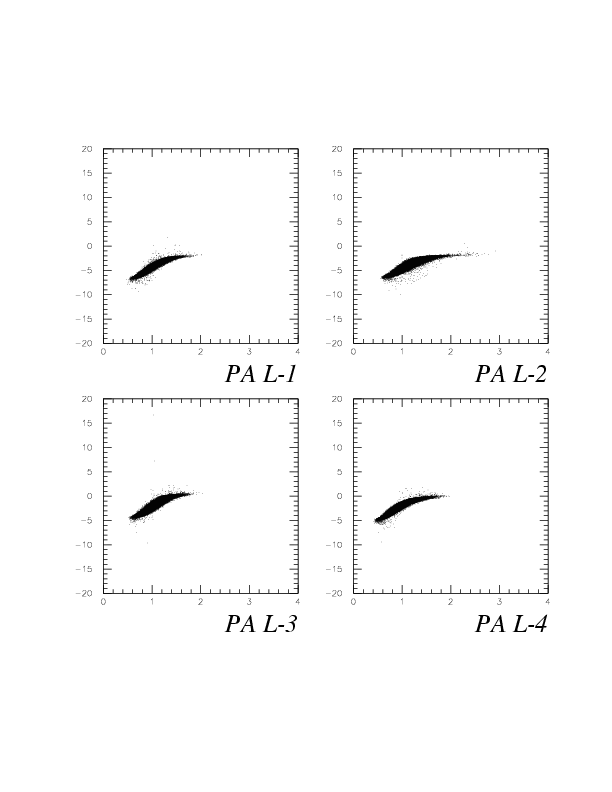
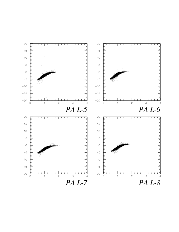
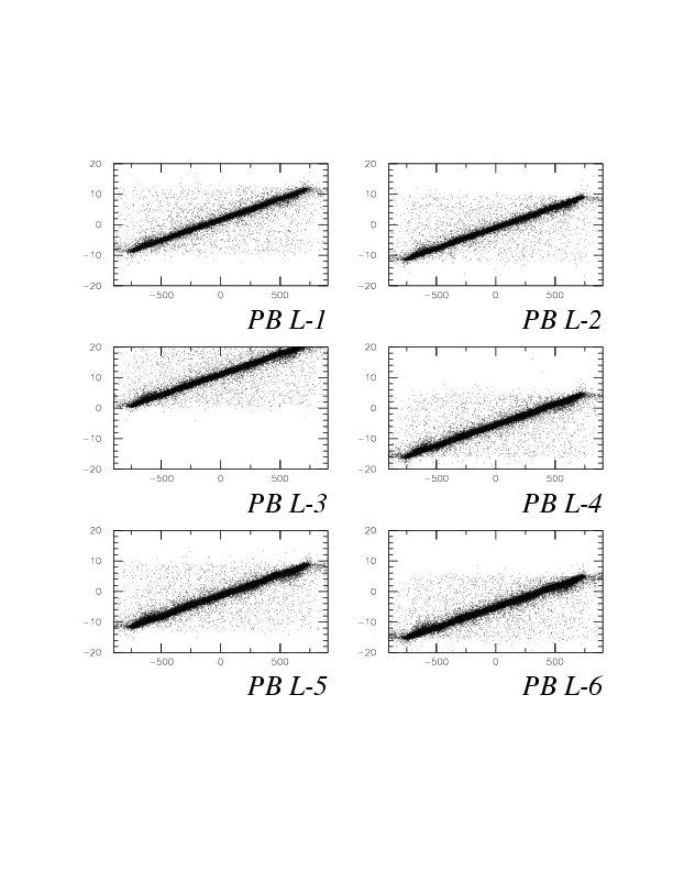
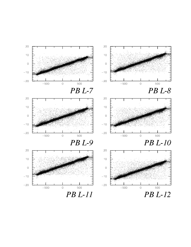
Nextly, we confirm the PB performance with the correlation between pulse hiight up/down ratio (horizontal) and down-up time difference (vertical), again. We should see a positive correlation for each counter, by which proper channel assignment is confirmed, and attenuation length is known. The counter performance of L-3, and L-14 are strange. The former is due to bud PMT used for top side, while the latter is not known ever. PB attenuation length is deduced to be about 2*L/ln(3.0/0.5) ~ 170 cm. The slope of the correlation is clearly larger than that for PA - that means PB behavier is fairly better than PA on attenuation.
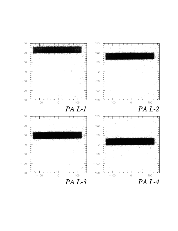
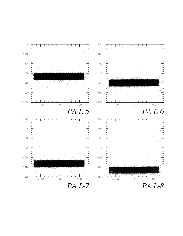
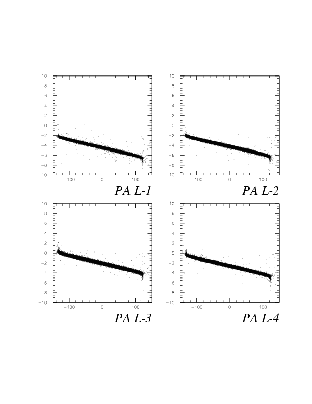
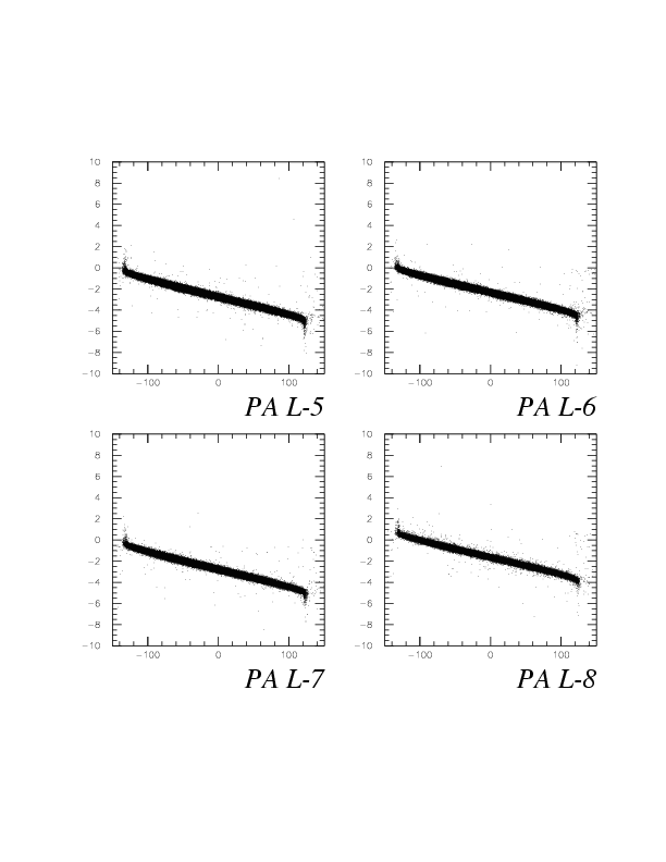
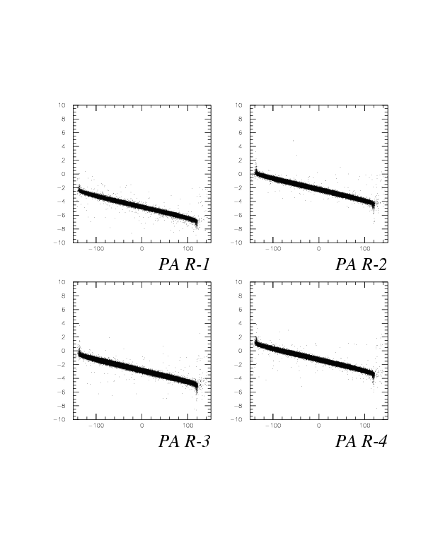
y/z consistency between PA/PB and detected PDC track is easily examined by y-z shadow of PDC track at PA/PB x position when the interested segment is fired.
Below, PA segment-by-segment y(vertical, mm) - z(horizontal, mm) shadows represented by E549 global coordinate system, are shown. PA and PDC track is confirmed to be consistent, for y direction.
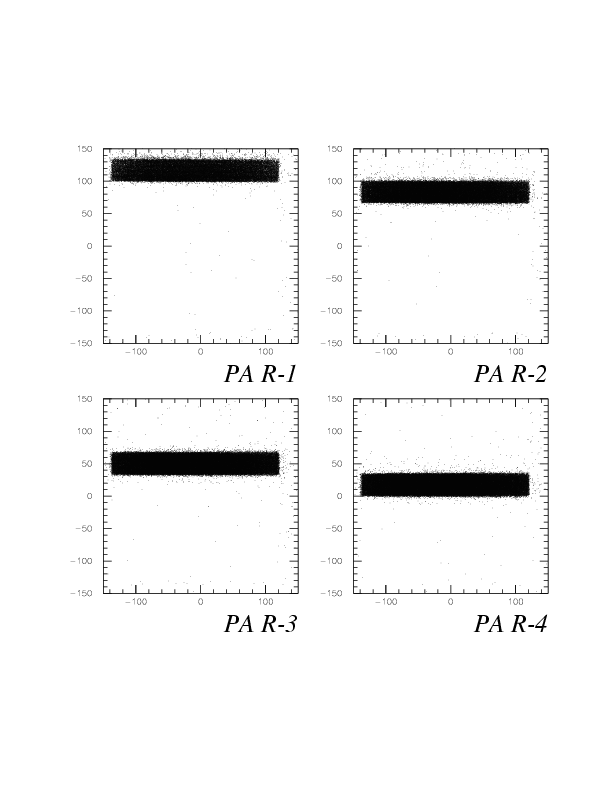
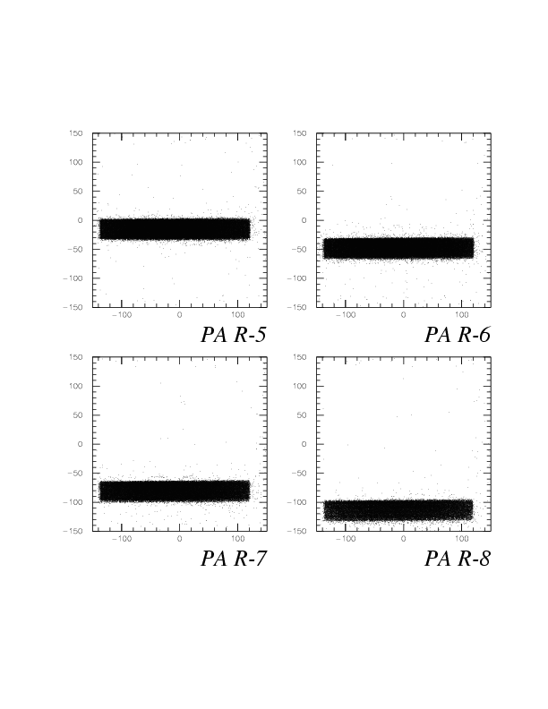
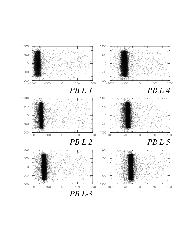
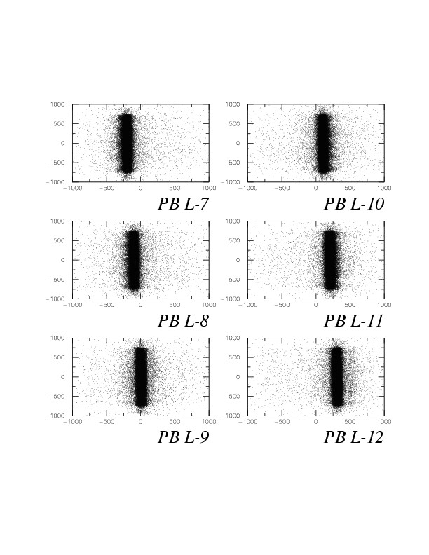
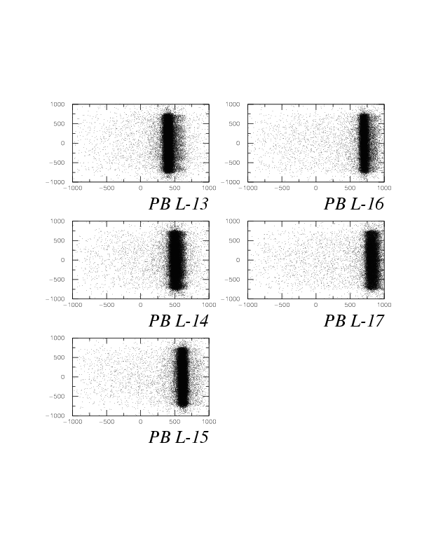
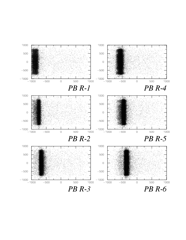
Below, PB segment-by-segment y(vertical, mm) - z(horizontal, mm) shadows represented by E549 global coordinate system, are shown. PB and PDC track is confirmed to be consistent, for z direction.
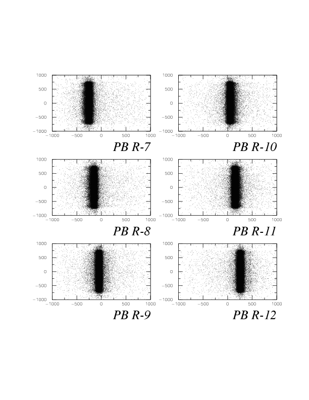
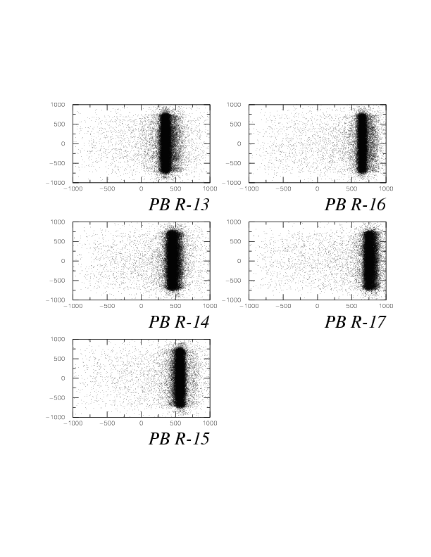
z/y consistency between PA/PB and detected PDC track is examined by the correlation between z/y shadow of PDC track at PA/PB x position when the interested segment is fired, and down-up time difference.
Below, PA segment-by-segment correlations between shadow z(horizontal, mm) and down-up time difference(vertical, nsec) are shown. PA and PDC track is confirmed to be consistent, also for z direction for all existing segments.
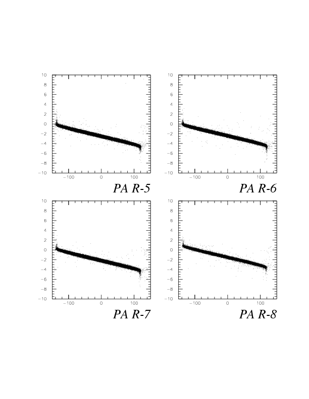
PB segment-by-segment correlations between shadow y(horizontal, mm) and down-up time difference(vertical, nsec) are shown. PN and PDC track is confirmed to be consistent, also for y direction for all existing segments.
By examinations performed above, geometrical consistency between PDC and PA/PB defined completely independently, is successfully confirmed and PA/PB performance has been known segment-by-segment.
Since we have 2(arms)*8(PA segments)*17(PB segments) PA-PB combinations, and combination-by-combination statistics for K^+ calibration run, 136-141, are not large enough, the analysis procedure to obtain accurate slewing parameters, time origins for PA-PB segments should be as follows. Note that all slewing parameters are determined PMT-by-PMT.
1. Perform PA-PB slewing correction for all 17 PB-segments with central PA segment, to adjust PB-by-PB time offsets and PB slewing parameters roughly.
2. After PB-by-PB time offsets has been eliminated, and (maybe in-accurate) PB slewing parameters are known, PA-by-PA slewing parameters and time offsets are adjusted with all PB segments, hence with large statistics.
3. PB-by-PB slewing correction for all 17 PB segments are performed, with all PA segments for which relative time offsets and slewing parameters are already known by the procedure 2.
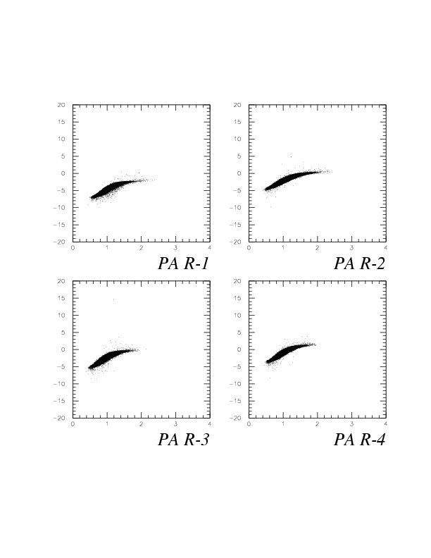
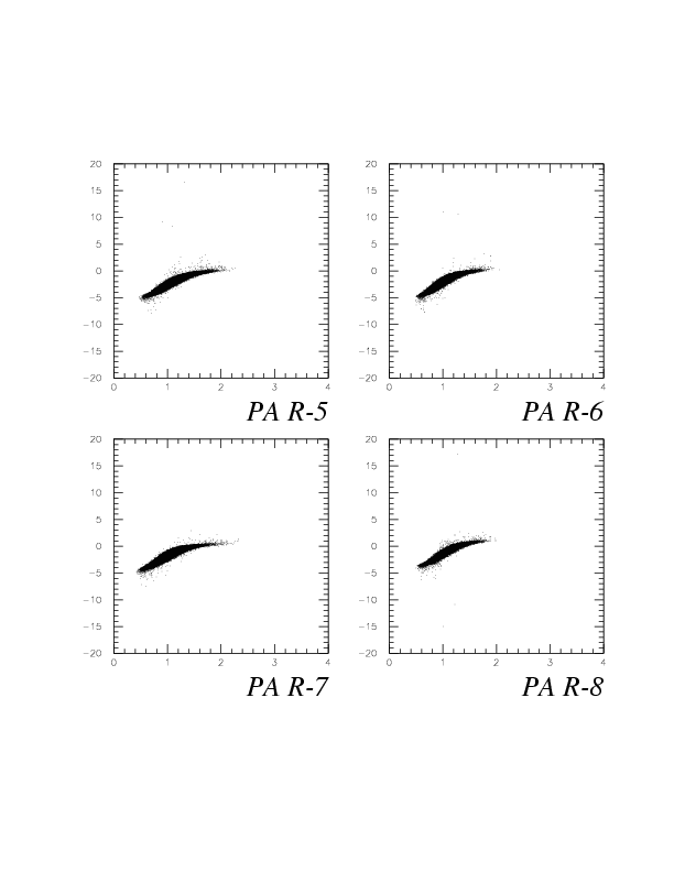
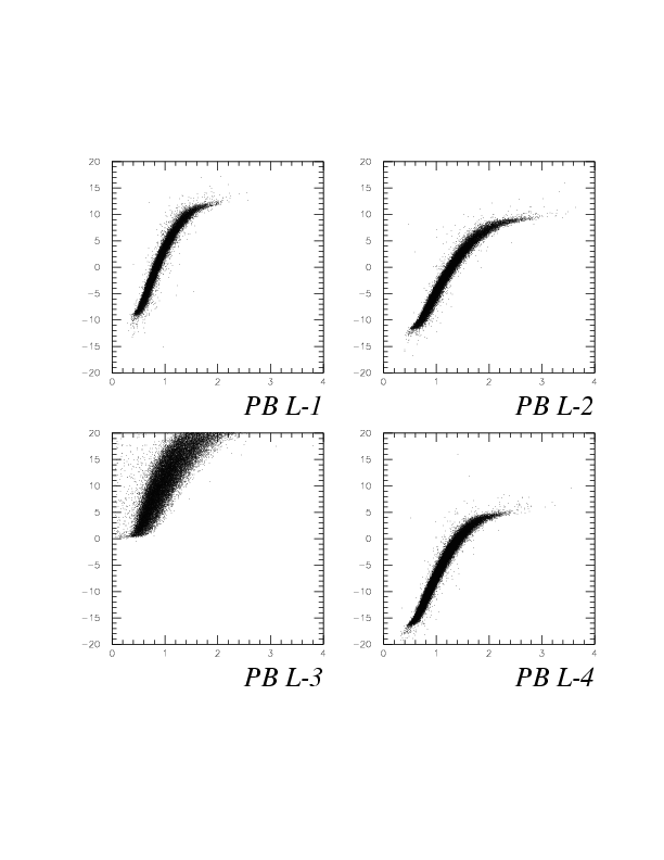
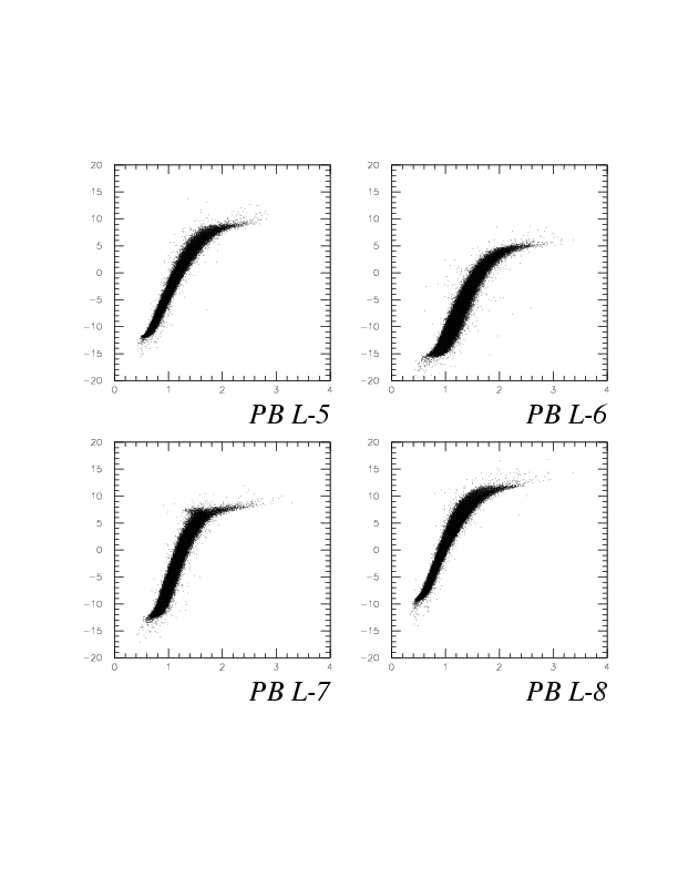
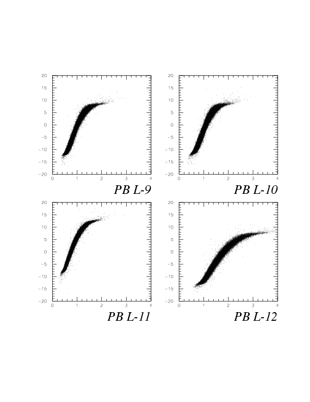
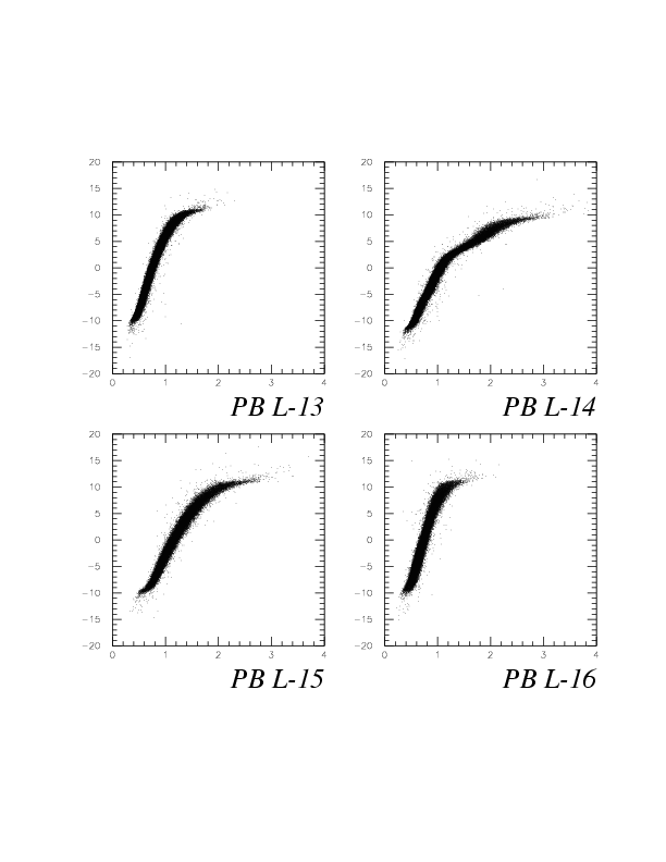
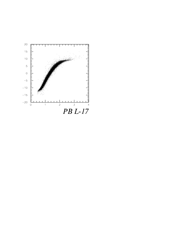
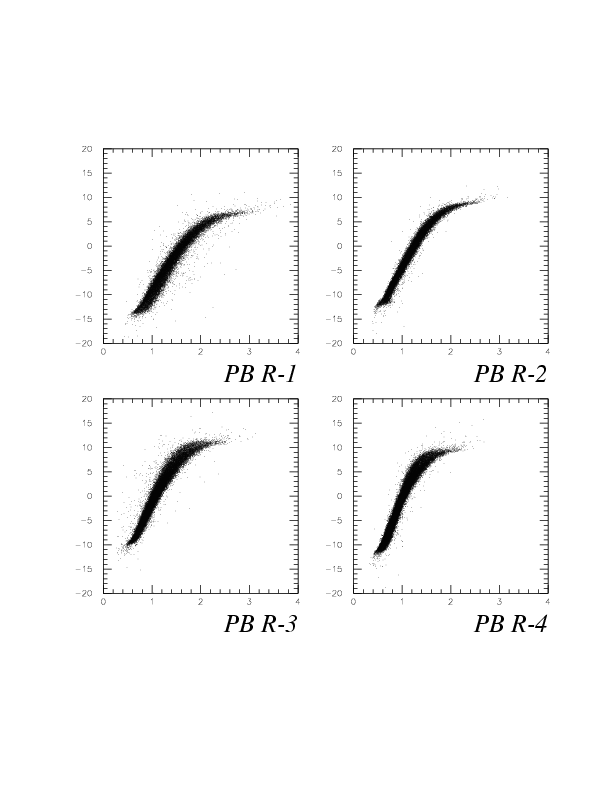
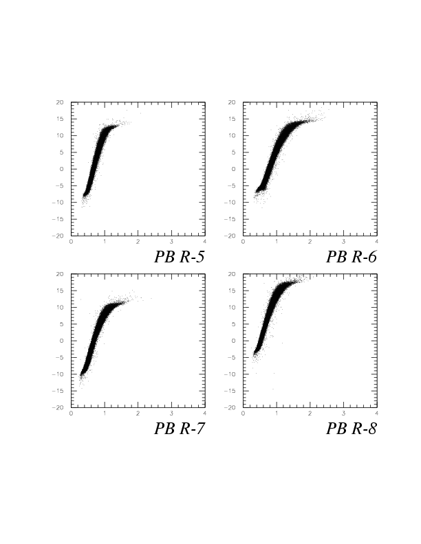
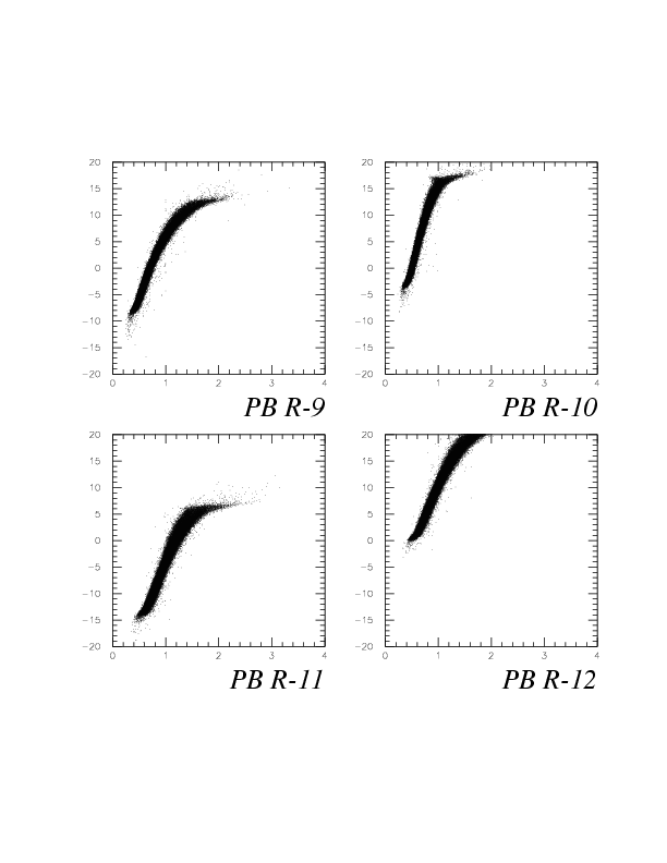
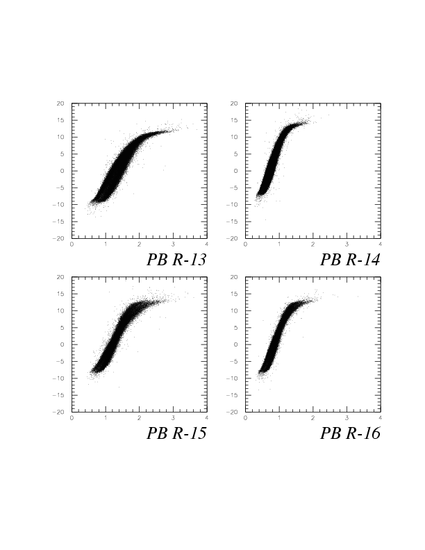
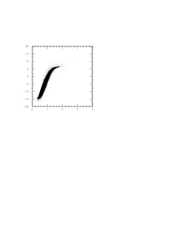
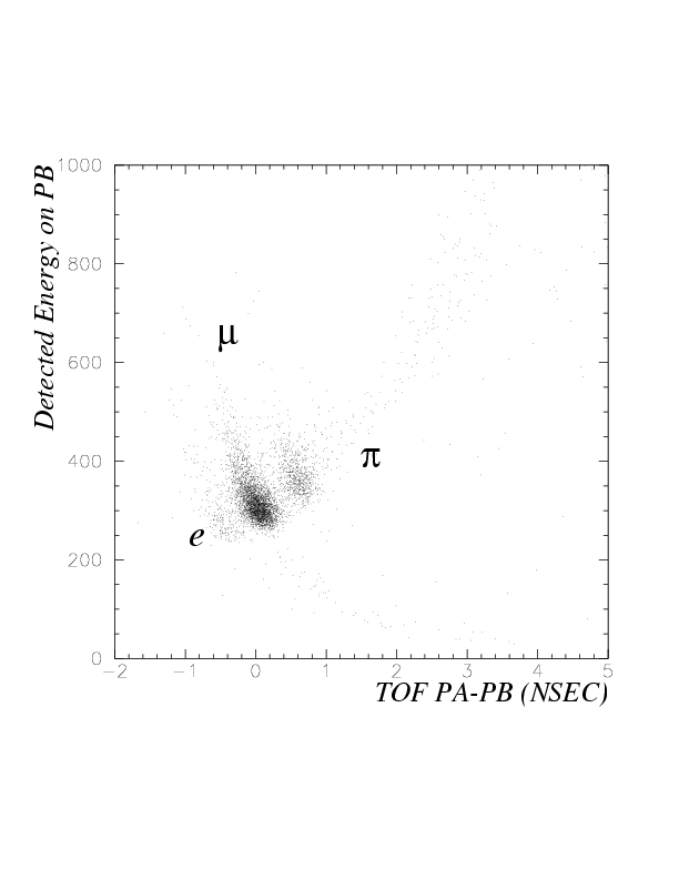
As shown below, muon, pion, electorn/positron from stopped K^+ decay can be discriminated by the correlation between TOF PA->PB before slewing correction and detected energy on PB segment fired. This may be the most general procedure to discriminate mu/pi/e, because the incident position dependence of the event selection is very small in this case, compared to the case in which NT multiplicity cut has been adopted instead.
The resulting slewing parameters of procedure1 are tabulatted below.
| PB arm | ROW | factor up | factor down | resolution (psec) | offset(nsec) | PA 4 factor up | PA 4 factor down | Event Number |
|---|---|---|---|---|---|---|---|---|
| L | 1 | 20.934 | 14.354 | 151.1 | 0.9934 | 10.623 | 8.861 | 1766 |
| L | 2 | 20.780 | 13.020 | 133.1 | 0.9944 | 10.125 | 6.840 | 2028 |
| L | 3 | 10.676 | 19.338 | 131.6 | 0.7135 | 9.540 | 8.972 | 2537 |
| L | 4 | 23.373 | 15.292 | 125.9 | 1.019 | 11.358 | 8.011 | 2969 |
| L | 5 | 21.262 | 15.118 | 126.7 | 0.9572 | 11.260 | 8.823 | 3197 |
| L | 6 | 30.192 | 5.374 | 122.8 | 1.013 | 9.881 | 9.060 | 3370 |
| L | 7 | 32.854 | 4.914 | 118.9 | 0.9967 | 9.935 | 9.658 | 3604 |
| L | 8 | 22.556 | 15.731 | 116.9 | 1.164 | 8.379 | 10.136 | 3428 |
| L | 9 | 22.414 | 13.211 | 115.9 | 0.8541 | 6.744 | 12.479 | 3630 |
| L | 10 | 21.267 | 15.845 | 126.0 | 0.5873 | 17.015 | 6.967 | 3487 |
| L | 11 | 22.403 | 12.575 | 114.9 | 1.022 | 7.442 | 10.733 | 3437 |
| L | 12 | 24.366 | 13.426 | 114.2 | 1.202 | 7.768 | 11.349 | 3292 |
| L | 13 | 21.742 | 13.304 | 113.6 | 1.000 | 7.660 | 12.365 | 2656 |
| L | 14 | 19.804 | 12.622 | 121.1 | 0.7247 | 6.953 | 12.046 | 2320 |
| L | 15 | 22.793 | 14.997 | 129.7 | 1.132 | 5.014 | 13.655 | 1858 |
| L | 16 | 17.958 | 16.874 | 132.2 | 1.044 | 7.757 | 11.396 | 1317 |
| L | 17 | 22.026 | 13.215 | 144.3 | 0.9183 | 9.793 | 10.923 | 1003 |
| R | 1 | 20.217 | 13.795 | 138.4 | 0.5688 | 10.851 | 13.003 | 1774 |
| R | 2 | 24.963 | 12.157 | 129.3 | 1.080 | 16.706 | 6.968 | 2046 |
| R | 3 | 24.398 | 10.535 | 127.3 | 0.4332 | 16.629 | 9.297 | 2446 |
| R | 4 | 23.813 | 17.300 | 115.5 | 0.9386 | 12.458 | 9.927 | 2938 |
| R | 5 | 16.987 | 18.018 | 114.4 | 0.7005 | 14.841 | 10.042 | 3410 |
| R | 6 | 25.063 | 10.824 | 107.7 | 0.8078 | 11.606 | 11.020 | 3398 |
| R | 7 | 20.524 | 14.657 | 105.1 | 0.9038 | 11.686 | 9.759 | 3531 |
| R | 8 | 22.839 | 14.849 | 105.5 | 0.8335 | 11.644 | 9.265 | 3562 |
| R | 9 | 22.788 | 14.959 | 101.5 | 0.7891 | 11.492 | 10.044 | 3560 |
| R | 10 | 22.289 | 14.644 | 98.8 | 1.007 | 11.493 | 10.153 | 3634 |
| R | 11 | 20.917 | 12.695 | 102.9 | 0.789 | 9.411 | 11.899 | 3688 |
| R | 12 | 20.209 | 19.066 | 101.5 | 0.9359 | 7.773 | 14.881 | 3495 |
| R | 13 | 21.585 | 10.137 | 106.2 | 0.5437 | 7.239 | 13.710 | 3162 |
| R | 14 | 21.218 | 10.512 | 109.7 | 0.5434 | 7.749 | 14.366 | 2542 |
| R | 15 | 14.765 | 14.754 | 128.1 | 0.4945 | 10.296 | 15.072 | 2038 |
| R | 16 | 21.406 | 8.002 | 119.4 | 0.5071 | 8.352 | 15.103 | 1512 |
| R | 17 | 22.820 | 11.450 | 124.2 | 0.6013 | 8.774 | 15.055 | 1239 |
Since slewing parameters for PB segments were roughly known by procedure 1, now we can determine PA slewing parameters accurately with full statistics available (from 17 PB segments). The result is tabulatted below.
| PA arm | ROW | Factor up | Factor down | Resolution (psec) | Offset(nsec) | Used Event Number |
|---|---|---|---|---|---|---|
| L | 1 | 7.262 | 16.215 | 141.6 | 3.897 | 22258 |
| L | 2 | 11.253 | 7.836 | 132.0 | 5.043 | 34712 |
| L | 3 | 9.411 | 13.825 | 133.5 | 4.604 | 43610 |
| L | 4 | 10.182 | 9.490 | 123.9 | 5.884 | 46001 |
| L | 5 | 11.192 | 12.682 | 134.4 | 5.076 | 47014 |
| L | 6 | 12.551 | 9.916 | 132.7 | 5.982 | 44187 |
| L | 7 | 12.186 | 10.189 | 146.0 | 5.775 | 36288 |
| L | 8 | 11.668 | 12.836 | 153.3 | 6.139 | 24352 |
| R | 1 | 11.573 | 8.937 | 130.9 | 5.063 | 23753 |
| R | 2 | 10.038 | 10.679 | 122.4 | 6.176 | 35803 |
| R | 3 | 11.401 | 11.778 | 121.4 | 5.637 | 45470 |
| R | 4 | 11.615 | 10.824 | 114.6 | 6.048 | 48766 |
| R | 5 | 11.114 | 10.997 | 117.9 | 6.092 | 48419 |
| R | 6 | 11.542 | 9.063 | 130.6 | 6.469 | 45033 |
| R | 7 | 12.395 | 7.901 | 123.1 | 6.139 | 35324 |
| R | 8 | 12.843 | 8.872 | 131.5 | 6.937 | 23221 |
Slewing parameters for PB segments are now determined with full statistics (8 PA segments). The result is tabulatted below.
| PB arm | ROW | Factor up | Factor down | mu peak width (psec) | pi peak width (psec) | Additional Offset(nsec) | Used Event Number |
|---|---|---|---|---|---|---|---|
| L | 1 | 19.854 | 14.348 | 172.1 | 172.4 | 0.71751E-01 | 11136 |
| L | 2 | 21.001 | 19.544 | 149.1 | 171.9 | -0.4056 | 12899 |
| L | 3 | 9.511 | 18.555 | 144.9 | 162.7 | 0.1108 | 16439 |
| L | 4 | 20.975 | 18.807 | 139.8 | 159.2 | -0.7031E-01 | 19293 |
| L | 5 | 20.132 | 17.915 | 135.3 | 158.9 | -0.9391E-01 | 20625 |
| L | 6 | 26.676 | 7.566 | 134.3 | 156.0 | 0.6536E-01 | 21815 |
| L | 7 | 27.543 | 9.855 | 127.7 | 156.0 | 0.4918E-02 | 22778 |
| L | 8 | 19.877 | 15.999 | 126.0 | 144.9 | 0.1419 | 22585 |
| L | 9 | 21.763 | 15.629 | 130.6 | 149.0 | -0.1016 | 22811 |
| L | 10 | 18.417 | 16.658 | 126.9 | 156.5 | 0.1170 | 22834 |
| L | 11 | 22.042 | 17.009 | 124.9 | 150.1 | -0.2217 | 22237 |
| L | 12 | 23.193 | 15.064 | 126.8 | 143.6 | -0.4824E-01 | 21136 |
| L | 13 | 22.680 | 15.651 | 128.0 | 155.5 | -0.1842 | 17471 |
| L | 14 | 20.203 | 17.876 | 135.4 | 157.6 | -0.3192 | 14918 |
| L | 15 | 23.347 | 17.941 | 139.1 | 160.1 | -0.1982 | 11704 |
| L | 16 | 19.066 | 18.305 | 144.4 | 166.6 | -0.1320 | 8685 |
| L | 17 | 16.981 | 15.583 | 154.0 | 169.2 | 0.1221 | 6359 |
| R | 1 | 16.757 | 16.039 | 146.7 | 169.3 | 0.4599E-01 | 10829 |
| R | 2 | 26.043 | 16.055 | 132.1 | 157.9 | -0.3012 | 12641 |
| R | 3 | 24.097 | 14.543 | 135.3 | 159.9 | -0.2134 | 15539 |
| R | 4 | 24.012 | 20.116 | 128.9 | 153.7 | -0.1603 | 18530 |
| R | 5 | 18.336 | 20.491 | 122.8 | 148.7 | -0.2181 | 20819 |
| R | 6 | 23.070 | 14.234 | 118.5 | 146.5 | -0.7859E-01 | 21569 |
| R | 7 | 19.863 | 17.372 | 117.0 | 140.5 | -0.1047 | 22292 |
| R | 8 | 22.605 | 15.450 | 117.3 | 140.2 | -0.1599E-01 | 22988 |
| R | 9 | 23.822 | 17.030 | 114.6 | 139.5 | -0.1636 | 22763 |
| R | 10 | 21.280 | 15.652 | 111.2 | 132.4 | 0.1539E-01 | 23587 |
| R | 11 | 20.356 | 15.339 | 116.2 | 135.7 | -0.1289 | 23284 |
| R | 12 | 19.587 | 20.424 | 113.9 | 134.1 | -0.4489E-01 | 22458 |
| R | 13 | 21.206 | 11.288 | 123.8 | 142.3 | -0.5353E-01 | 19772 |
| R | 14 | 18.684 | 15.027 | 128.0 | 146.9 | -0.9875E-01 | 16390 |
| R | 15 | 15.552 | 16.792 | 133.4 | 160.2 | -0.1815 | 12627 |
| R | 16 | 13.376 | 14.198 | 139.9 | 147.4 | 0.1109 | 9793 |
| R | 17 | 20.391 | 13.268 | 147.6 | 169.5 | 0.3392E-01 | 7908 |
Clear dependence of the resolution on PA and PB segment position is seen, which inplies the particle incident angle or position dependence of the time resolution , which will be studied in near future. Furthermore, we do need complete PID for the study of higher-order-slewing correction fuctors, but we do need well-separated e/mu/pi peaks by 1/beta(or TOF), then. At this moment, it is not achieved yet.
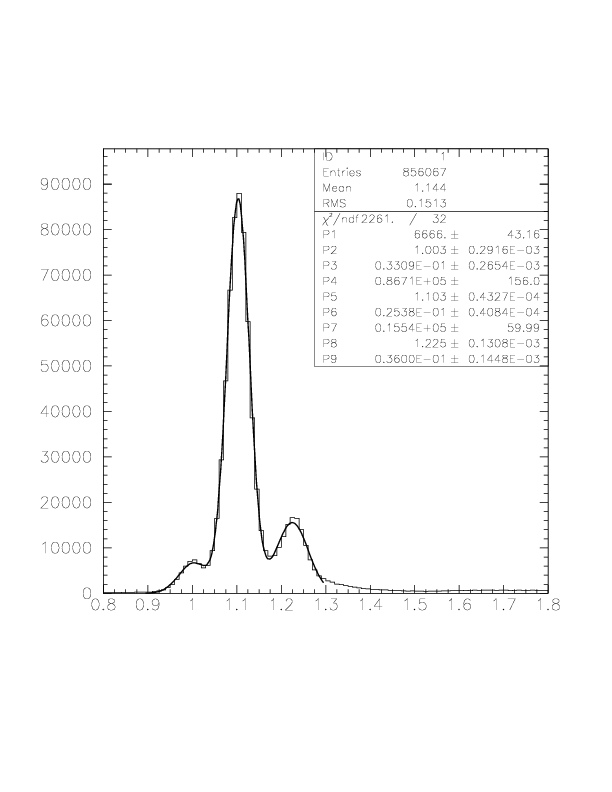
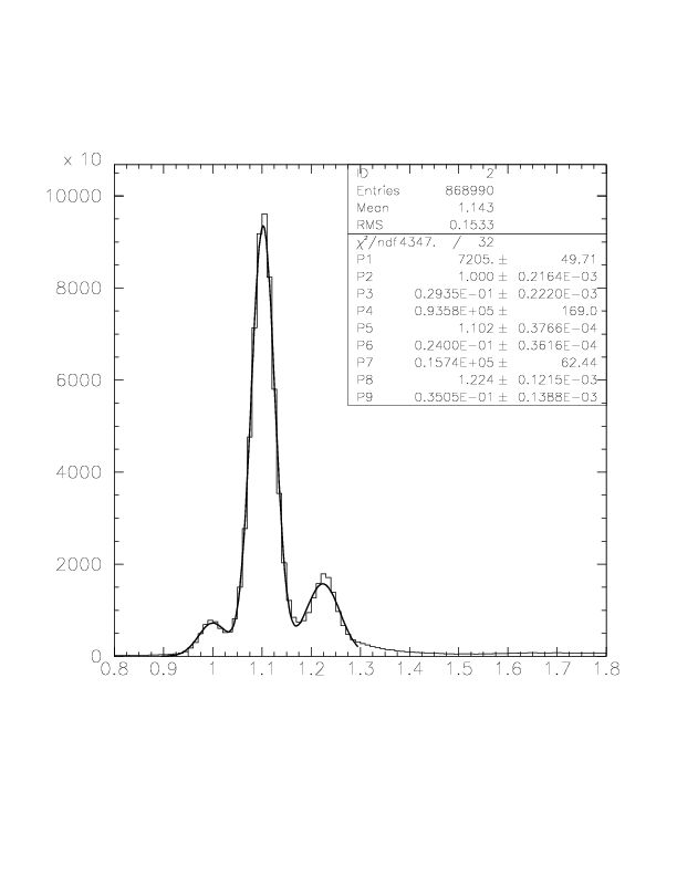
The resulting arm-by-arm 1/beta spectra are shown below. P2, P5, and P8 are e/mu/pi peak center, respectively, while P3, P6, and P9 are Gaussian widths for those three peaks. The overall resolutions, which are defined by the Gaussian sigma values for muon peaks, are 0.0254 and 0.0240, then. Note that TOF offset is just adjusted to make muon 1/beta peak center position to be 1.1017. Then, electron and pion peaks are automatically at the expected position.